Electric motors convert electrical energy into rotational mechanical power. However, the motor is just the beginning of an industrial drive system. Power transmission components send rotation to the driven machine. They also manage speed, torque, direction, and mechanical connections. A typical system has a motor shaft, a coupling, a gearbox, a secondary shaft, and a mounted gear, pulley, or sprocket. The connection between those parts matters as much as the individual components. A poorly matched keyway, spline, bore, or shaft can lead to assembly issues. It can also affect how the system transmits torque.
For engineers, OEMs, machine builders, and manufacturers, the main question isn’t just about picking a motor. Look at the entire system—from the motor’s output, through the transmission, to the final driven part.
This guide explains how electric motors and power transmission operate. It covers the main parts, the role of keyways and splines in torque transfer, and how various applications use these interfaces. It also shows what engineers need to consider when selecting and creating precision internal profiles.
Key Takeaways
- An electric motor creates rotational power. This power goes into the transmission system via its shaft.
- Power transmission components pass rotation to the driven equipment. They can also change speed, torque, direction, or the drive’s location.
- Keyways and splines are vital connections between shafts and hubs. They are commonly found in gears, pulleys, sprockets, couplings, and other rotating parts.
- Keyways form a keyed link, while splines connect parts with several teeth and grooves.
- The right connection depends on a few key factors: torque, shaft shape, load, axial movement, fit, material, production needs, and inspection standards.
- Broaching and vertical slotting create internal keyways, splines, grooves, and special profiles. The right method depends on the part and production needs.
How Do Electric Motors and Power Transmission Work Together?
An electric motor converts electrical power into rotational mechanical power. The motor shaft delivers that rotation to the next component in the drive system. The U.S. The Department of Energy views the motor and its connected equipment as part of a bigger motor-driven system, rather than just a separate device. The transmission path then carries that mechanical output to the load.
A simplified arrangement is:
Electric motor → motor shaft → coupling or mounted part → gearbox or transmission → shaft/hub link → driven equipment
Not every machine uses every component. A motor can drive a pump directly with a coupling. Another machine might use a gearbox, secondary shaft, pulley, or sprocket to deliver the load. Torque and speed don’t always stay the same in the system. A gearbox lowers rotational speed and boosts output torque. Also, a belt, chain, or gear setup can adjust the speed connection between shafts.
You need to check the connection at the end of the transmission path. Focus on the actual torque and loading at that point, not just the motor’s nameplate rating.
Common Electric Motor Types
Motor selection hinges on a few key factors: the electrical supply, load needs, speed, control method, duty cycle, environment, and application.
AC Motors
AC motors are common in industrial equipment. Induction motors are commonly used in pumps, fans, compressors, conveyors, and other machinery. Synchronous motors offer various operating features. You can choose them when their speed or performance matches the needs of your application. The key idea in power transmission design is that the motor’s output traits serve as inputs for the mechanical system.
DC Motors
DC motors operate from direct-current power and can provide useful speed-control characteristics. They are still used in some equipment and older setups. However, many modern industrial systems now prefer AC motors with electronic controls.
Servo and Brushless Motors
Servo systems are used where controlled motion, positioning, or speed is important. Brushless motors use electronics for commutation instead of mechanical parts. They are great for applications needing controlled and efficient rotary motion. No matter the motor type, the mechanical transmission must fit the shaft output and provide the needed motion to the load.
Electric Motor Types Comparison Table
| Motor Type | Main Characteristic | Typical Applications | Transmission Consideration |
| AC Motor | Reliable, efficient, widely used | Pumps, fans, conveyors | Often paired with gearboxes, couplings, belts or direct drives |
| DC Motor | Simple speed control | Battery-powered and variable-speed equipment | Transmission depends on required speed and torque |
| Servo Motor | Precise speed and position control | Robotics, CNC, automation | Requires precise coupling and shaft connection |
| Brushless Motor | Efficient, low maintenance | Automation, machinery, compact equipment | Suitable where controlled speed and efficient power transfer are important |
What Components Are Used in Power Transmission Systems?
Power transmission systems use various parts to transfer mechanical power from the motor to the equipment it drives. Their functions overlap in some systems, but each solves a different mechanical problem.
Shafts
Shafts carry torque and rotational motion between components. A motor shaft may connect to a coupling, gearbox, pulley, sprocket, gear, or another rotating element. Shaft design involves more than nominal torque. Engineers should think about several factors. These include bending loads, bearing locations, fatigue, and shaft diameter. They must also consider keyway or spline geometry, component fit, surface condition, and how loads enter the shaft. This is particularly important when an internal profile is machined into a hub or other component that mounts to the shaft.
Couplings
Couplings connect two shafts and transfer rotation between them. Their design can sometimes manage misalignment or impact how vibrations travel. The coupling itself is only part of the interface. Its bore and connection method must correspond with the shafts being joined. A mismatch in bore size, keyway shape, spline specs, or fit can lead to assembly problems, even if the coupling looks correct.
Gearboxes
Gearboxes alter the relationship between input and output speed and torque.
For an ideal mechanical transmission:
P = Tω
where P is mechanical power, T is torque, and ω is angular velocity. For example, consider a hypothetical motor delivering mechanical power at 1,800 rpm. If a reduction gearbox has an output speed of 900 rpm, the output torque is about double the input torque. This is before considering any transmission losses.
This shows a key design principle: the torque felt by a downstream shaft or hub can be very different from the torque at the motor shaft. The system must consider efficiency, operating loads, starting conditions, shock loads, and the gearbox ratio.
Example:
Suppose an electric motor produces 15 kW at 1,800 RPM.
Torque can be estimated using:
Torque (N·m) ≈ 9,550 × Power (kW) ÷ RPM
So:
Torque ≈ 9,550 × 15 ÷ 1,800
Torque ≈ 79.6 N·m
Now suppose a gearbox reduces speed from 1,800 RPM to 900 RPM, giving a 2:1 reduction ratio.
Ignoring losses, output torque approximately doubles:
Output Torque ≈ 79.6 × 2 = 159.2 N·m
Gears, Pulleys, and Sprockets
Gears transfer motion through tooth engagement. Pulleys transfer motion through belts, while sprockets engage chains. These parts can send power between shafts. They also change speed or torque based on their sizes or gear ratios. Each component also needs an appropriate connection to its shaft. That connection may use a keyway, spline, clamping arrangement, or another engineered interface.
Power Transmission Components Table
| Component | Primary Function | Common Application | Key Design Consideration |
| Shaft | Transfers rotational power | Motors, gearboxes, machines | Torque, diameter, alignment |
| Gearbox | Changes speed and torque | Conveyors, machinery | Ratio, torque capacity, efficiency |
| Coupling | Connects rotating shafts | Motor-to-machine drives | Alignment, flexibility, torque |
| Hub | Connects components to a shaft | Wheels, pulleys, sprockets | Bore, fit, keyway/spline |
| Keyway | Secures hub to shaft | Pulleys, gears, couplings | Torque, fit, geometry |
| Spline | Transfers torque through multiple teeth | Heavy-duty drives | Profile, fit, load distribution |
How Keyways and Keys Transmit Torque
A keyway is a machined groove in a shaft or mating hub that accommodates a key. The key connects features in the shaft and mounted part. This creates the right mechanical link for transmitting torque. For example, a pulley mounted on a shaft may contain a hub bore with a keyway that corresponds to the shaft keyway. The key fits into the mating grooves so the shaft and pulley rotate together.
The keyway is therefore a functional feature of the assembly, not simply a slot. Its width, depth, location, fit, and how it relates to the bore and mating part all must meet the engineering requirements. Poor dimensional control can lead to problems. It can make assembly hard, create too much clearance, cause unwanted movement, or result in undesirable loading. A feather-key arrangement may allow axial movement when the shaft, key, and mating hub are specifically designed for sliding while maintaining torque transmission. The right question is not simply whether a keyway can be machined. It checks if the key-and-keyway interface meets the assembly’s requirements.
How Do Splines Transmit Torque?
Splines use multiple teeth or ridges around a shaft that engage corresponding grooves in a mating component. A spline has several engagement points around its circumference, unlike a single keyed slot.
Common spline forms include:
- Involute splines
- Straight-sided splines
- Serrated splines
The chosen spline shape affects how the parts fit together and how loads are shared. Splines are useful for designs that require a multi-tooth interface for torque transmission. They have a compact shape and let you control axial movement when needed. They are also found in mechanical assemblies with gears, hubs, couplings, and other rotating parts. However, a spline is not automatically the better choice.
Spline manufacturing needs special tools and precise profile control. It also requires careful inspection and more detailed specifications than standard keyed connections. The right choice depends on a few factors: the application’s torque, shape, movement needs, manufacturing limits, and service conditions.
Keyway vs. Spline: How Should Engineers Choose?
Consider the function of the connection when choosing between a keyway and a spline. Don’t just rely on the machining processes you have available. A keyed connection is effective when a standard shaft-and-hub setup can manage sufficient torque. This is true if the design doesn’t need the features of a multi-tooth spline. A spline works well when multiple teeth can engage properly. It’s also good when space or shape suits a multi-tooth connection. Lastly, it’s useful when controlled axial movement is needed in the design.
Engineers should work through these questions:
1. How much torque must the interface transmit?
Start with the torque actually reaching the connection. If a gearbox, gear train, belt drive, or chain drive changes the torque before reaching the component, use the downstream operating condition. Don’t just copy the motor-shaft value.
2. What shaft and hub geometry is available?
The connection needs to fit the shaft diameter and hub wall thickness. It must also meet the mechanical design requirements.
3. Is axial movement required?
If the component must stay fixed along the axis, you could pick another connection method. This would be better than one that allows for controlled sliding.
4. What loading will the connection experience?
Steady rotational loading differs from cyclic, reversing, impact, or shock loading. The connection needs to be evaluated for the actual service conditions.
5. What fit and alignment are required?
The mating components need compatible dimensions and an appropriate fit. A keyway or spline specification may be correct in theory, but it won’t work if the mating parts don’t match.
6. How will the feature be manufactured?
Process selection is influenced by several factors: production volume, profile complexity, tolerance requirements, material, feature accessibility, tooling availability, and part geometry.
7. How will the finished feature be inspected?
For a key transmission part, the inspection should check features that ensure proper connection and function. This selection process avoids a common mistake. It doesn’t choose the connection first and then tries to fit the manufacturing process later.
Electric Motor Power Transmission Applications
The same basic motor-to-load principle shows up in many industrial applications. However, the transmission path can vary greatly.
Pumps
A motor may connect directly to a pump through a coupling or drive another shaft through a transmission arrangement. The shaft connection must maintain the right link between the motor and pump. It also needs to handle the application’s operating conditions.
Conveyors
Conveyor systems usually use motors with gearboxes, shafts, sprockets, chains, pulleys, or other drive parts. A keyway or spline connects a rotating part to the shaft that carries the torque.
Machine Tools
Machine tools need controlled speed and torque. This is done through a spindle or transmission system. Internal profiles in gears, hubs, or couplings can be crucial to the entire drive setup.
Fans and Blowers
Fans and blowers may use direct-drive or shaft-driven arrangements. The part where a pulley, coupling, or other piece connects to the motor or shaft must fit the system’s mechanical needs.
Industrial Drive Assemblies
Gearboxes, reducers, motors, couplings, shafts, gears, and hubs can be combined in many configurations. The farther the driven component is from the motor, the more important it is to know how speed, torque, and loading change along the transmission path. These examples show why choosing an electric motor and designing power transmission need to go hand in hand.
Why Precision Matters in Power Transmission Components
A motor can work well, but the mechanical transmission may still have issues due to a poor interface. Consider a gear with an internal spline. The motor might give the right power, and the gearbox might deliver the needed torque. But the gear still needs to fit properly with its shaft. The same applies to a pulley with an internal keyway or a sprocket mounted on a driven shaft.
Problems can arise from:
- Incorrect keyway width or depth
- Incorrect feature location
- Mismatched spline geometry
- Unsuitable fit
- Poor alignment
- Inadequate dimensional control
- Improper consideration of material or loading
- Manufacturing methods that do not suit the required profile
This is why internal profiles should be treated as functional engineering features. A drawing must include the dimensions, tolerances, profile requirements, and instructions for making and checking the feature. The manufacturer should know if the feature is blind or through and how it works in the final assembly.
Keyway and Spline Broaching for Power Transmission Components
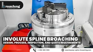
Broaching uses a toothed cutting tool. It shapes internal profiles by slowly removing material. Internal broaching is used for features such as keyways and spline profiles. For manufacturers, the attraction is not simply that broaching is fast. This process is useful for consistently creating a specific internal profile in production parts.
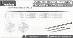
Keyway broaching can produce the internal slot required for a keyed shaft-and-hub connection. Spline broaching makes the internal tooth profile needed to fit a splined shaft.
The manufacturing sequence can be viewed as:
Part function → drawing/specification → material → profile → tooling → setup → cutting → inspection
That sequence matters because cutting is only one step in creating a working transmission component. Broaching Technologies, LLC offers keyway broaching, spline broaching, blind-hole broaching, internal shape cutting, and custom broaching as part of its services. The company also provides tooling and setup support and broach re-sharpening and maintenance services.
When Should Vertical Slotting Be Considered?
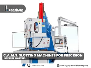
Vertical slotting is another way to create internal grooves, keyways, splines, and special profiles. The appropriate choice depends on the part rather than a blanket rule that one process is always superior. Vertical slotting is great for flexible machining. It helps create special internal shapes and allows for precise tool movement and positioning. Broaching Technologies provides C.A.M.S. Vertical slotting machines come with features such as an electronic tool lift, programmable stroke control, and one to four NC-controlled axes, depending on the model. Its published machine range also offers electronic turntable options for grooves and splines.
This creates an important manufacturing decision:
Choose the method that fits the geometry, production conditions, tooling needs, and size goals best.
A manufacturer shouldn’t pick broaching, slotting, or any machining method just because they’re used to it.
Common Power Transmission Manufacturing Mistakes
Designing the Connection Around Motor Power Alone
Motor horsepower or rated output doesn’t tell the whole story about the load on downstream parts. Transmission ratios and operating conditions can change torque throughout the system.
Treating a Keyway as a Generic Slot
The size, position, fit, and relationship of the keyway to the mating part are essential requirements.
Assuming Every Spline Is Interchangeable
Spline profiles are defined by specific geometry and specifications. Two components that both appear to have “splines” may not be compatible.
Ignoring the Part’s Manufacturing Route
A suitable profile must also be manufacturable. This includes meeting requirements for tolerances, production volume, material, accessibility, and tooling limits.
Providing Incomplete Drawings
A nominal bore and feature name might not give enough details to create a vital internal profile. The applicable dimensions, tolerances, profile information, material, and functional requirements should be clear.
What Information Should You Provide for Keyway or Spline Manufacturing?
A productive manufacturing discussion starts with complete part information. For a keyway, provide the relevant drawing, shaft or bore dimensions, keyway dimensions, location, material, tolerance requirements, and whether the feature is blind or through.
For a spline, provide the spline specification, tooth geometry, dimensions, fit requirements, material, and any relevant inspection requirements. Production quantity also matters because tooling and process selection can change with volume.
It is useful to explain the component’s role as well. A hub for a conveyor drive, a gearbox gear, and a coupling part can have different needs. This is true even if their shapes appear similar. If the feature is in a motor-driven power system, sharing the app’s needs helps the manufacturing team choose the right process.
How Broaching Technologies Supports Motor-Driven Power Transmission Components
Broaching Technologies focuses on the internal features that connect many power-transmission components. Its published contract machining capabilities include keyway broaching, spline broaching, blind-hole broaching, internal shape cutting, vertical slotting, and custom broaching. The company also supports tooling and setup requirements and provides access to C.A.M.S. vertical slotting technology.
The relevance to electric motor power transmission is the mechanical interface. A motor can be bought as a standard part. However, the gear, pulley, sprocket, hub, coupling, or any other rotating part linked to that motor may need a specific internal profile. That is where the manufacturing decision becomes important.
Broaching Technologies has a team of machinists and engineers. They have many years of practical experience in keyway broaching, spline broaching, and slotting system design. It also identifies itself as the exclusive North American dealer for C.A.M.S. vertical slotting machines.
For a manufacturer, the appropriate next step is not simply to ask whether a feature can be cut. The goal is to check if the process and tools fit the part’s shape, tolerance, material, quantity, and function.
A Practical Decision Sequence for Motor-Driven Components
When developing or sourcing a part for an electric motor power transmission system, follow this order:
Define the load. Determine the required speed, torque, duty cycle, and loading conditions.
Map the transmission path. Identify the positions of the motor, gearbox, coupling, shaft, gear, pulley, sprocket, and other components in relation to each other.
Identify the critical interfaces. Determine which connections require keys, splines, clamping, or another method.
Define the internal profile. Specify the keyway, spline, groove, or special shape needed and how it relates to the part.
Select the manufacturing process. Think about broaching, vertical slotting, or another method. Choose based on geometry, material, tolerance, volume, tooling, and accessibility.
Define inspection requirements. Check the dimensions and features to confirm before assembling the component.
This sequence is better than choosing a machining method first. It links the manufacturing decision directly to the finished machine.
Conclusion
Electric motors supply the mechanical input for many industrial drive systems. However, the motor is just one part of the power-transmission chain. Shafts, couplings, gearboxes, gears, pulleys, sprockets, and shaft-to-hub connections control how power gets to the driven equipment.
For engineers and manufacturers, the main issue is usually how those components connect. Keyways and splines need to match their parts. They should handle the required load and movement. Also, they must be made to the specifications of the finished assembly.
That makes process selection part of the engineering decision. Broaching, vertical slotting, and other machining methods need evaluation. Consider the internal profile, material, tolerance, production quantity, tooling, accessibility, and inspection requirements.
Broaching Technologies supports manufacturers with contract keyway and spline broaching, blind-hole broaching, internal shape cutting, vertical slotting, custom broaching, and related tooling and setup support.
If your motor-driven component has a keyway, spline, blind internal feature, groove, or special profile, check with Broaching Technologies about the part requirements before selecting the final manufacturing process.
Frequently Asked Questions
What is the relationship between an electric motor and power transmission?
The electric motor converts electrical power into rotational mechanical power. The power transmission system moves that rotation to the driven equipment using parts like shafts, couplings, gearboxes, gears, belts, chains, pulleys, and sprockets.
What is the most important connection between a motor and a transmission?
There is not one universal connection. The motor can connect to the machine in several ways. These include a coupling, direct shaft connection, gearbox, keyed component, spline, or another designed interface. The correct arrangement depends on the application.
Are keyways and splines interchangeable?
No. A keyway uses a key in a machined groove, while a spline uses multiple mating teeth and grooves. Their dimensions, fit, geometry, and intended applications differ.
Is a spline always stronger than a keyway?
No universal rule makes one automatically stronger. A spline spreads engagement over several teeth. However, its performance relies on geometry, materials, loading, fit, engagement, and overall design.
When is keyway broaching used?
Keyway broaching makes internal keyways in parts like hubs, gears, pulleys, sprockets, and couplings. This is needed when a keyed shaft connection is required.
When is spline broaching used?
Spline broaching is used to produce internal spline profiles that mate with corresponding splined components. The spline’s specifications, geometry, material, tolerances, and production needs shape the manufacturing method.
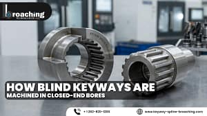
Can internal blind keyways be manufactured?
Yes. Blind internal features need a manufacturing method and tools that fit their depth, shape, access, and process needs. Broaching Technologies specifically lists blind-hole broaching among its contract capabilities.
What information should be provided when requesting broaching?
Provide the part drawing, material, profile requirements, dimensions, tolerances, production quantity, and whether the feature is blind or through. For splines, include the applicable spline specification and geometry. Explaining the component’s function can also provide useful engineering context.
Is vertical slotting an alternative to broaching?
It can be, depending on the component and requirements. Before choosing a process, check these factors: geometry, production volume, tooling, accessibility, tolerances, and machine capability.