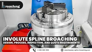
Involute spline broaching is a precision machining process used to form multiple, evenly spaced teeth inside a bore. Those teeth mate with an external spline to transmit torque while helping the connected parts maintain alignment.
The process can produce repeatable internal profiles for power-transmission components. Success depends on aligning the spline specification, starting bore, material, access, tooling, datums, and inspection method.
For engineers and buyers, the key question is not only whether the spline can be broached. It is whether the part is defined for reliable manufacturing, inspection, and assembly.
Key Takeaways
- Involute spline broaching forms a curved tooth profile that supports torque transfer across several mating teeth.
- A quote-ready drawing should define the governing standard, tooth count, pitch system, pressure angle, fit, diameters, spline length, datums, and inspection requirements.
- Through splines and blind splines require different access, tool travel, and chip-control strategies.
- Inspection planning should begin before tooling is designed, not after the first parts are produced.
- Material, heat-treatment sequence, annual volume, tolerance class, and tooling ownership can all affect feasibility, cost, and lead time.
What Is Involute Spline Broaching?
An involute spline has curved tooth flanks based on involute geometry, similar to the profile used on many gears. When an internal spline mates with an external spline, contact occurs along the tooth flanks. The connection can transfer rotary motion and torque through several teeth rather than concentrating the load at one key.
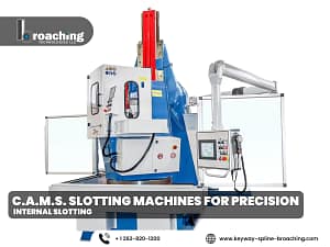
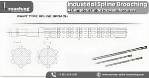
Broaching creates the internal spaces that form those teeth. In a conventional progressive broaching process, a series of cutting teeth removes material in controlled increments until finishing teeth establish the required profile. Other vertical slotting strategies may generate the spaces through repeated, controlled cutting strokes. The correct method depends on the part, feature access, quantity, tolerance, and available tooling.
This article focuses on straight, non-helical internal involute splines. Helical forms, external splines, and unusual profiles can require different equipment and process planning.
If you are still deciding between spline forms, read the separate guide to involute, parallel, and serration splines. That page owns the profile-selection question. This guide focuses on making and inspecting an involute profile after the design direction is established.
Why Manufacturers Use Involute Splines
An involute spline distributes torque across multiple tooth flanks. Its geometry can also support centering and controlled fit when the mating parts, tolerances, and assembly are designed correctly.
Common applications include gears, hubs, couplings, drive components, pumps, motors, and other power-transmission equipment. Each assembly still requires its own evaluation of load, duty cycle, speed, lubrication, alignment, environment, and movement.
Some assemblies need clearance for installation or axial movement. Others require tighter positional control. A note such as “spline to match shaft” does not define the tooth thickness, space width, backlash, or acceptance method.
When Is Broaching a Good Manufacturing Choice?
Broaching is worth evaluating when a part needs a repeatable internal spline and the expected quantity can justify dedicated tooling or a controlled slotting setup.
The method becomes less straightforward when:
- The bore is blind or lacks tool exit space
- The spline is very short, very deep, or interrupted
- A shoulder blocks the required cutting travel
- The wall is thin enough to risk distortion
- Material hardness creates an unsuitable cutting condition
- Heat treatment may change the finished geometry
- The drawing leaves the mating fit or inspection method undefined
- Production quantity does not justify the proposed tooling route
These conditions do not automatically disqualify a part, but they require an early design-for-manufacturability review. A change to a relief, chamfer, pilot bore, datum, or process sequence may improve feasibility before tooling is committed.
When geometry or volume makes the route unclear, compare broaching with shaping, slotting, wire EDM, skiving, or another suitable process. Select the method against the full drawing and production requirement.
Design Information to Define Before Tooling
The toolmaker and contract broaching supplier need an unambiguous definition of the finished internal spline. The following inputs have the greatest influence on planning.
1. Governing spline standard
State the standard and revision that control the design. Existing North American inch-based drawings may reference ANSI B92.1-1996, Involute Splines and Inspection, which ANSI currently labels historical. Confirm that it is the required contract reference instead of assuming it governs a new design. Metric side-fit designs may reference the ISO 4156 series. ISO 4156-3:2021 addresses inspection of straight cylindrical involute splines with metric module and side fit.
Do not combine values from different standards without a complete engineering definition. Similar labels do not always create interchangeable geometry or acceptance limits.
2. Tooth system and basic geometry
Depending on the selected standard, the drawing should identify:
- Number of teeth
- Diametral pitch or metric module
- Pressure angle
- Major and minor diameters
- Pitch or reference diameter
- Tooth thickness or internal space width
- Root and form details where required
- Spline length and its location in the bore
The callout may control several values, but the drawing must still identify the applicable revision and toleranced features.
3. Fit, centering, and backlash
Define how the members must assemble and function. In a side-fit spline, the tooth flanks control the mating relationship. The tolerance class influences clearance, backlash, and effective engagement.
Do not choose a tighter class by default. It can increase tooling and inspection demands without improving the assembly. Fit should follow the mechanism’s load, alignment, movement, and service needs.
4. Starting bore and tool access
The supplier needs the starting-bore diameter, tolerance, condition, depth, and relationship to the part datums.
Also show:
- Entry chamfer or lead-in
- Through-hole or blind-bore condition
- Tool exit and chip-relief space
- Shoulders, counterbores, cross-holes, or interrupted sections
- Maximum available stroke or access constraints
- Wall thickness around the spline
A drawing showing only the finished teeth can hide the feature that controls the manufacturing route.
5. Material and heat-treatment condition
Specify the workpiece material, grade, hardness range, and condition at the time of broaching. “Steel” is not a complete cutting specification.
Heat-treatment sequence also matters. Broaching before hardening may improve machinability, but later treatment can alter size or form. Broaching afterward creates different tooling demands. Agree on the sequence before production.
6. Datums, concentricity, and runout
The spline does not function in isolation. Its axis may need a controlled relationship to a bearing diameter, pilot, face, or another rotating feature.
Use a clear datum reference frame. A spline can pass a size gauge while the part still fails to assemble or rotate if its axis is not properly related to other features.
How the Involute Spline Broaching Process Is Planned
A disciplined process usually follows five stages.
1. Drawing and manufacturability review
The supplier reviews the callout, mating requirements, material, bore, tolerances, quantities, and inspection plan before tooling design.
At this stage, the team also decides whether the requested geometry suits through broaching, a vertical slotting approach, or a specialized blind-feature method.
2. Tooling, fixture, and bore preparation
The tool must reproduce the tooth spaces while managing cutting load, chips, strength, and wear. The fixture supports the part and aligns the bore with the cutting path.
The prepared bore is equally important. Incorrect size, position, roundness, or surface condition can change the resulting spline or overload the tool.
3. Controlled material removal
Material is removed in planned increments. A progressive broach distributes the cut across roughing and finishing teeth. An indexed slotting process generates each space through controlled strokes.
Cutting fluid, alignment, machine rigidity, chip load, and chip evacuation must remain stable. Changes in these conditions can affect profile, size, finish, and tool life.
4. Cleaning and edge finishing
After machining, chips and fluid are removed. Controlled deburring must protect the functional tooth geometry.
5. Inspection and process feedback
The finished spline is checked against the drawing and quality plan. First-piece results guide any approved setup correction. A gauge can test an effective assembly limit, while analytical measurements help locate pitch, profile, lead, or runout error.
Through Splines and Blind Splines Need Different Plans
A through bore allows the tool and chips to move beyond the full spline length. That access can simplify tool travel and chip removal. A blind spline stops before the opposite face of the part. The tool cannot simply pass through the workpiece, and chips do not have the same exit path. Bottom clearance, relief geometry, cutting depth, and chip evacuation become central design inputs.
Do not assume a through-broaching setup can be shortened and used for a blind feature. Blind work needs a process designed around the closed end. Broaching Technologies has a separate resource on blind-hole broaching for keyways and splines for projects with that geometry.
Plan Spline Inspection Before the Tool Is Built
Inspection is not a final administrative step. It defines what the tool and process must produce. A functional go/no-go spline plug gauge can provide a fast attribute check of assembly-related limits. However, a gauge alone may not explain why a part does not fit. Elemental or analytical inspection may be needed to evaluate tooth thickness or space width, index, lead, involute profile, concentricity, and runout.
The appropriate plan depends on the drawing, standard, risk, quantity, and customer quality requirements. AGMA 945-1-B20 provides broader guidance on the design, manufacturing, inspection, failure, and troubleshooting of spline connections. The applicable product drawing and purchase requirements still control the job.
Before ordering tooling, agree on:
- The governing standard and tolerance class
- Functional gauge requirements
- Elemental measurements required for approval
- Datum setup for runout or concentricity checks
- Sampling frequency
- First-piece or first-article documentation
- Any customer-specific reporting or record-retention rules
Do not request PPAP, FAI, CMM data, or a full analytical report by assumption. State each deliverable that the program actually requires and confirm supplier capability.
Common Causes of Nonconforming Internal Splines
Many spline problems begin before cutting. Common causes include:
- Incomplete or conflicting callouts: The drawing, model, and purchase order disagree on the standard, class, pressure angle, pitch system, or fit.
- Incorrect starting bore: An oversized, undersized, tapered, or mislocated bore changes tool load and the finished geometry.
- Misalignment or weak fixturing: Poor axis control can cause runout, uneven tooth form, or an incorrect relationship to other features.
- Material variation: Changes in grade, hardness, heat treatment, or stock condition alter cutting behavior.
- Poor chip control: Packed or recut chips can damage deep or blind features.
- Tool wear or damage: Wear can change size, profile, finish, and cutting load during repeat production.
- Inspection that misses function: A part may pass a size check but fail assembly because index, profile, lead, or concentricity was not controlled.
What Affects Involute Spline Broaching Cost and Lead Time?
There is no responsible universal price for an involute spline. Cost and scheduling depend on the specific manufacturing route.
Key factors include:
- Standard or custom tooth geometry
- Tool availability and tooling ownership
- Through or blind feature access
- Spline length, bore size, and part geometry
- Material grade and hardness at machining
- Fit class and geometric tolerances
- Fixture complexity
- Inspection gauges and reporting
- Prototype, release, and annual production quantities
- Tool maintenance or reconditioning needs
Dedicated tooling can be a larger upfront item, but it may support efficient repeat production when volume and design stability justify it. Lower or uncertain quantities may favor a different cutting strategy. The quote should separate tooling, setup, per-part processing, inspection, and any special documentation so buyers can compare complete scope.
What Should You Send for an Involute Spline Broaching Quote?
A complete request reduces clarification cycles and helps the supplier evaluate the correct process. Send:
- A controlled 2D drawing and available 3D model
- The spline standard, revision, and complete callout
- Tooth count, diametral pitch or module, and pressure angle
- Fit or tolerance class and centering method
- Major diameter, minor diameter, and spline length
- Starting-bore specification
- Through or blind condition, including relief and tool access
- Workpiece material, grade, hardness, and heat-treatment sequence
- Datum, runout, and concentricity requirements
- Functional gauge and analytical inspection requirements
- Prototype quantity, release quantity, and estimated annual volume
- Required first-piece documents or customer quality clauses
- Mating-part information when fit questions remain
- Target delivery date and any fixed program milestones
Broaching Technologies’ contract broaching team can use this information to review manufacturability and identify unanswered questions. A drawing review is not a substitute for the customer’s design authority, but it can expose manufacturing conflicts before tooling and production.
Experience Matters Most Before Production Starts
The expensive spline problems are often not the visible ones. A missing relief, unclear fit, unsuitable inspection plan, or heat-treatment conflict can remain hidden until tooling or first pieces are complete.
Broaching Technologies operates from Menomonee Falls, Wisconsin, in the Milwaukee area. The company brings more than 30 years of hands-on experience in broaching, slotting, and tooling applications. Its published capabilities include spline broaching services, contract broaching, blind-hole work, tooling support, and production-oriented review.
If you are preparing an internal involute spline for prototype or repeat production, send the drawing and program requirements for a feasibility and quoting discussion.
Frequently Asked Questions
What is involute spline broaching?
Involute spline broaching is a machining process that forms multiple curved-flank tooth spaces, typically inside a prepared bore. The finished internal spline mates with an external spline to transmit torque and control alignment according to the specified fit.
What information defines an involute spline?
The definition starts with a governing standard, tooth count, diametral pitch or module, and pressure angle. It also covers the major and minor diameters, tooth thickness or space width, fit class, centering method, and spline length. Drawing requirements vary by standard and application.
Can a blind internal involute spline be broached?
Some blind internal splines can be produced with specialized tooling and controlled vertical slotting or blind-broaching methods. Feasibility depends on depth, bottom relief, bore access, chip evacuation, material, and tolerance requirements.
How are broached involute splines inspected?
Inspection may combine a functional go/no-go spline plug gauge with elemental or analytical measurements. The plan can include effective fit, space width, index, lead, profile, concentricity, and runout, depending on the drawing and quality requirements.
Should an involute spline be broached before or after heat treatment?
There is no universal sequence. Broaching before heat treatment may improve machinability, while heat treatment can later affect size or form. Broaching after heat treatment changes cutting and tooling demands. The material, hardness, tolerance, and distortion risk should guide the plan.
Does a spline plug gauge provide a complete inspection?
Not always. A functional gauge is valuable for verifying defined assembly-related limits, but it may not identify the cause of a failure. Analytical measurements may be required when profile, index, lead, or runout must be evaluated separately.