If you have ever taken apart a gearbox or looked closely at a motor shaft, you have probably seen a small rectangular slot cut into it. That slot is a keyway. And that tiny groove plays a much bigger role than most people realize.
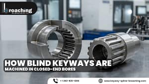
Keyways in mechanical engineering are machined slots cut into a shaft or a hub – sometimes both – that hold a small metal piece called a key. That key sits between the shaft and the hub, and it is the only thing stopping them from spinning independently of each other. Without it, your gear, pulley, or sprocket would just rotate freely on the shaft like a loose wheel on an axle. No torque would be transferred. The machine would be useless.
It sounds simple. And in concept, it is. But getting keyways right – the right type, the right dimensions, the right fit, the right material – takes real understanding. That is exactly what this guide is here to give you.
Why Engineers Still Trust Keyways After All These Years
You might wonder why, in an age of precision splines, hydraulic couplings, and interference fits, engineers still use keyways so widely. The answer is straightforward: keyways work, they are affordable, and they are easy to deal with when something goes wrong.
A keyed connection gives you a positive mechanical lock. It does not rely on friction like a shrink fit does. It does not depend on adhesive that can degrade over time. It physically blocks rotation. That means it can handle sudden torque spikes, reversing loads, and shock conditions that would destroy softer connection methods.
There is also the maintenance factor. When a machine needs to come apart for a repair or an overhaul, a keyed shaft is straightforward to disassemble. Slide the hub off, pull the key out, and you are done. Compare that to breaking an interference fit – which often requires a hydraulic press and a lot of patience.
So yes, keyways in mechanical engineering have been around for well over a century. And they are not going anywhere.
The Main Types of Keyways – And When to Use Each One
Not all keyways are the same. Different designs exist for different load types, shaft geometries, and assembly requirements. Here is a breakdown of the ones you will encounter most often:
| Keyway Type | Shape | Common Use Case |
| Parallel Keyway | Rectangular slot | General-purpose power transmission |
| Woodruff Keyway | Semi-circular slot | Tapered shafts, automotive applications |
| Tapered Keyway | Wedge-shaped profile | Heavy shock loads, self-tightening fits |
| Gib-Head Keyway | T-head key profile | Where blind removal is needed |
| Spline Keyway | Multiple teeth around shaft | High torque, precision alignment needs |
Parallel keyways are the workhorses. You will find them on almost every type of rotating shaft in industrial machinery. They are easy to machine, easy to source keys for, and covered by well-established international standards.
Woodruff keyways have a half-moon shape. The key itself sits deeper in the shaft, which helps it self-align in tapered shaft assemblies. You see them frequently in automotive work – on crankshafts, camshafts, and steering columns.
Tapered keyways are older in design but still used in specific applications. The wedging action of a tapered key creates a self-tightening fit, which can be useful where vibration is present. The downside is that they can be harder to remove.
Gib-head keyways are essentially tapered keys with a protruding head on one end. That head gives you something to pull against when removing the key – particularly useful in blind assemblies where you cannot tap the key out from the other side.
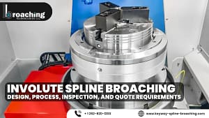
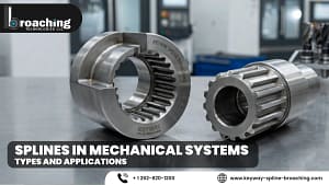
Spline connections are what you turn to when a single keyway is not enough. Instead of one key and one slot, splines have multiple teeth running along the shaft. They distribute the load evenly and allow for much higher torque capacity.
How Keyways Are Actually Cut
The geometry of a keyway looks simple on a drawing, but machining it accurately is a different story. The method you choose affects surface finish, dimensional accuracy, production speed, and cost.
Broaching – Fast, Accurate, and Ideal for Bores
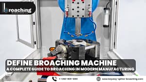
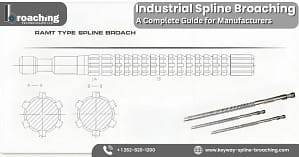
Broaching is the go-to method for cutting keyways inside bores and hubs. A broach is a long cutting tool with progressively deeper teeth. You push or pull it through the bore in a single stroke, and each tooth removes a little more material until the finished keyway is cut.
The result is exceptional. Broached keyways have excellent surface finish, consistent dimensions across a production run, and very tight tolerances. If you need hundreds of identical hub keyways cut quickly and accurately, broaching is the right answer.
At Keyway Spline Broaching, broaching is a core service – and the precision they deliver reflects how seriously the process needs to be taken when dimensional accuracy matters.
Milling – Flexible and Widely Available
For shaft keyways, milling is the standard approach. An end mill or a Woodruff cutter is used on a milling machine to cut the slot to the required depth and width. With a CNC milling machine, you can hold very tight tolerances and produce clean keyway profiles with good repeatability.
Milling is more flexible than broaching because you are not committed to a specific broach size. You can cut different keyway widths just by changing the end mill. That makes it ideal for prototype work, small batches, or custom one-off shafts.
EDM – For Hard Materials and Tight Spaces
Electrical discharge machining removes material through controlled electrical sparks rather than physical cutting. It is slower than broaching or milling, but it shines in situations where the workpiece is extremely hard, or where the geometry makes conventional cutting impossible.
Hardened steel components that cannot be softened without distortion are a typical use case. EDM can cut a keyway in a fully hardened shaft without creating the cutting forces that would chip a conventional tool.
Keyway Tolerances – Why Getting the Fit Right Is Everything
Here is where a lot of problems happen. A keyway that looks fine on the surface can cause real damage if the fit is wrong. Too tight and you cannot assemble the joint without damaging the key or the bore. Too loose and you get fretting, micro-movement, wear, and eventually fatigue cracking around the keyway.
The internationally recognized standards for keyway fits are ISO 773 and DIN 6885. These define three basic fit categories:
Clearance Fit (Free Fit): There is a slight gap between the key and the keyway. Assembly is easy, but this fit is only appropriate for light-duty applications or where the direction of torque does not reverse.
Transition Fit (Normal Fit): This is the standard fit for most power transmission applications. There is minimal clearance or slight interference depending on the actual dimensions, but assembly is still practical with hand tools or a light press.
Interference Fit (Tight Fit): The key is larger than the keyway by a controlled amount. Assembly requires pressing, and the resulting joint can handle heavy shock loads and reversing torque reliably.
Choosing the wrong fit class is not a minor detail. It is the kind of decision that determines whether your keyway lasts ten years or fails in ten weeks.
Design Details That Separate Good Engineers from Careless Ones
Knowing that a keyway is a slot is one thing. Designing one that survives in service is another. Here are the design details that actually matter:
Stress Concentration at Corners
A sharp inside corner on a keyway is a stress riser. Under cyclic loading, cracks initiate at these corners and propagate into the shaft. Specifying a proper fillet radius – even a small one – dramatically reduces the stress concentration factor and significantly improves fatigue life. Never leave this to chance.
Keyway Width and Depth Relative to Shaft Diameter
These are standardized values for a reason. The standards exist because decades of engineering experience and testing have established what proportions work. Do not try to freelance these dimensions unless you have very specific reasons and have done the stress calculations to back them up.
Length of the Keyway
The keyway needs to be long enough to spread the torque load across a sufficient contact area. If the engagement length is too short, the bearing stress on the keyway sidewalls will exceed the material’s capacity, and the keyway will wallow out.
Two Keyways for High Torque
When a single keyway is not enough, two keyways placed 180 degrees apart is a better solution before jumping to a full spline. The load splits between the two keys, reducing the stress on each one.
Industries Where Keyway Quality Directly Affects Safety
Keyways in mechanical engineering are not just an academic topic. In real-world applications, keyway failures cause downtime, costly repairs, and sometimes serious safety incidents.
- Automotive: Transmission shafts, power takeoff drives, steering rack gears
- Aerospace: Actuator drive shafts, flight control surface mechanisms
- Oil and Gas: Compressor shafts, pump drives, wellhead equipment
- Power Generation: Steam turbine shafts, generator rotors, cooling fan drives
- Manufacturing: Conveyor systems, press drives, gearbox output shafts
- Agriculture: PTO shafts on tractors, harvester header drives, irrigation pumps
In all of these applications, a failed keyway does not just mean a machine stops. It means unplanned downtime, potential injury, and repair costs that dwarf what proper machining and inspection would have cost in the first place.
If you are working in any of these sectors and need precision keyway work, Keyway Spline Broaching is a resource worth bookmarking.
Common Keyway Problems and How to Prevent Them
Even well-designed keyways can develop problems over time. Knowing what to look for helps you catch issues before they become failures.
Fretting Wear: Small relative movement between the key and keyway sidewalls causes fretting – a form of surface damage that looks like reddish-brown powder. It is caused by a loose fit or insufficient torque transmission relative to the applied load. Fix it by specifying a tighter fit class or a larger key.
Keyway Broaching: When the keyway widens over time due to the key rocking back and forth under reversing loads, the joint becomes progressively looser. The right solution is to redesign the connection for the actual load – not just replace the key.
Fatigue Cracking: Cracks starting at keyway corners under cyclic bending loads. Prevention comes down to proper fillet radii, surface finish, and keeping bending moments at keyed sections as low as possible through good shaft design.
Corrosion and Fretting Together: In environments where moisture can enter the keyway, fretting and corrosion combine into a particularly destructive process. Proper sealing, compatible materials, and appropriate surface treatments are your tools here.
Frequently Asked Questions
Q: What is the difference between a keyway and a keyseat?
A: Keyway refers to the slot in the hub or bore. Keyseat refers to the slot in the shaft. Both together form the complete keyed joint.
Q: How do I know what keyway size to use for a given shaft diameter?
A: Use DIN 6885 or ASME B17.1. Both standards provide tables that specify key width, height, and keyway depth based on shaft diameter ranges.
Q: Does a keyway weaken the shaft?
A: Yes, it reduces the shaft cross-section and introduces a stress concentration. Good design practice – including proper fillet radii and correct keyway proportions – minimizes this effect significantly.
Q: Can you recut a worn keyway?
A: Sometimes, but each recut removes more material and weakens the shaft further. In most cases, replacing the shaft or hub is the more reliable long-term solution.
Q: What is the most common cause of keyway failure?
A: Incorrect fit tolerance is the most common root cause – usually a fit that is too loose, which allows micro-movement and eventually leads to fretting and fatigue.
Conclusion
There is nothing flashy about a keyway. It is a simple slot in a shaft or a bore. But as this guide shows, keyways in mechanical engineering carry a tremendous amount of responsibility in every machine they are part of. The type you choose, how it is cut, how accurately the tolerances are held, and how thoughtfully the design is detailed – all of it feeds directly into whether the machine performs reliably or develops problems that are frustrating and expensive to fix.
Treat keyways as a serious engineering feature, not an afterthought. Specify them correctly, machine them precisely, and inspect them properly. That approach will always pay off in longer service life and fewer unexpected failures.